EMC RFI
shielding - Laminated Window & Display
EMC RFI
shielding of a display filter screen or window can be achieved by
incorporating either a conductive coating or a metal mesh
layer in the window. Both options must be grounded to the
frame of the device to give an effective emc display shield.
High levels of emc attenuation can be acheived using
EMI mesh laminates.
We also supply the EMI mesh seperately,
click here for info
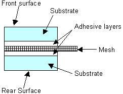
The attached diagram illustrates the basic design:

Dimensions
| Substrate |
Min.
Laminate thickness |
Max.
Laminate Size |
|
| Glass |
1.7mm |
950
x 1500mm |
| Polycarbonate |
1.2
- 1.6mm |
950
x 1500mm |
| Acrylic |
1.2
- 1.6mm |
850
x 850mm |
|
Surface
finish
It
is important to select the most suitable surface finish
for each application.
Emi/rfi
shielding element
There
are a variety of mesh types and conductive coatings that
are specified for emc shielded windows.
Meshes are traditionally specified in terms of
material, wire treatment, count (opi) and thickness. These
meshes are usually made from stainless steel or copper
wires that can then be coated and blackened to prevent
surface reflections.
VisionTek
Systems offers EmiClare™, a new generation of
emi windows using a mesh that has been specifically
designed for shielding displays. This mesh provides high
levels of emi/rfi
shielding whilst preserving the brightness and clarity
of the display. These windows do away with complicated and
unnecessary specification of wire count (opi), thickness
and treatment. You simply need to specify EmiClare mesh
and the angle of the mesh that you require. Click
here for emi/rfi shielding performance information.
Standard
conductive coatings are ITO (indium tin oxide) with about
15 ohms/square and AgF8 with 8 ohms/square.
Termination
Methods for emi shielded windows
There
are several forms of termination in use for shielded
windows. Detailed here are those methods that are cost
effective and have proven, with over eleven years of
applications experience, to provide an efficient
termination.
Mesh
extensions can be specified for glass and plastic
windows. If properly installed into the aperture they
yield a higher rf attenuation than a busbar / gasket
combination. This edge form is recommended for large
format windows and low frequency applications.
 |
Square
edge with a mesh extension |
 |
Step
edge with a mesh extension |
Machined
Edges, Busbar and Gasket
|
 |
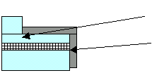
| The
laminate build and the step profile
must be co-ordinated to ensure that
the step finishes in a substrate |
The
busbar must include the face that
sections the mesh. Depending on the
termination required it could be
extended over one or both surfaces of
the window. |
|
 |
| If
a gasket is used, the step depth
should be designed to allow for the
correct compression of the gasket |
On compression the conductive surface
of the gasket should maximise contact
area with the busbar. |
|
Termination
methods for mesh extension windows
|
 |
The
most effective termination is to clamp the mesh
extension to the enclosure. This can be done for
windows with either a step or a square edge. This
termination is not possible with the new
generation ultra-fine meshes. |
 |
An
effective compression gasket can be formed by
taking the mesh over a compression gasket material
such as neoprene. |
 |
A
mesh extension can be combined with a silver
busbar and a conductive compression gasket. Unless
there is a special gasket requirement, this
termination is not recommended on the basis of
cost. It is effective if a combination gasket is
required to give both an environmental and rfi
seal. |
 |
For
large windows such as rack enclosure doors, a cost
effective option is to cut the mesh extension
close to the edge of the window and finish it with
a conductive tape carried over to both faces of
the window. This is preferable to a simple mesh
extension, which from our experience, is often
torn when handling large windows. |
Termination
of conductive coatings
|
 |
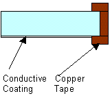
A
conductive coating can be terminated by a
conductive tape which contacts the coating. This
can be carried to the front face of the window if
required. For applications where the conductive
coating might be subject to environmental damage,
it can be laminated to the inside of the window
and either exposed on the edge of a step or by
using a silver busbar wrapped from the conductive
surface onto the rear surface prior to lamination |
Handling
All
filters are packaged with a protective foil on both sides
or wrapped in tissue. We recommend that the filters are
stored like this.
For
all filters, try to limit the number of occasions the
filter is handled as this can easily damage it. A few
important hints are listed hereunder:
- Handle
filters by holding at the edges
- Do
not remove the protective foil until final
installation of the filter. Inspect the filter by
holding it at the edges and peeling back the foil
halfway. Replace the foil and then repeat for the
other half of the filter.
- Inspection
should be carried out in a clean, dust-free
environment. Always use lint free wipes or dry
compressed air.
- Always
ensure that the filter is placed on a clean, dust-free
surface.
Handling
techniques for specific materials
- Plain
glass - Clean with a cloth or a tissue. Use any glass
cleaner
- ITO
coated glass - Do not touch the surface as it is very
soft. Do not use any cleaning fluids. Dust can be
removed by blowing with clean air.
- MLAR
coatings - Do not touch as fingerprints are made
highly visible by low reflection properties. Clean
with a glass cleaner and rub gently with a clean
cloth. Take a second cloth to remove all traces of the
cleaner and to polish.
- Acrylic
- clean with IPA and a clean lint free cloth
- Polycarbonate
- Surface dust can be removed with compressed air.
Hard coated and non-glare polycarbonate can be cleaned
with a dry cloth. Do not use any alcohol based
cleaners.
- Polyester
- Clean with IPA and a clean cloth. AgF8 coated
polyester should be handled as for ITO coatings.
|